Writing a CHIP-8 "emulator" in C
Part 1
Virtualization always seemed like magic (still does), but as I'm reading Operating Systems: Three Easy Pieces, I've started thinking more about it, and realizing that I've slowly been understanding small parts of it, bit by bit.
So I wanted to figure out how it's implemented on a basic level, and building a small emulator like this is, in my opinion, a great way to do so without too much pain.
Big disclaimer, to get ahead of pendantic mfs, this is technically not an emulator, as an emulator emulates another program or device, CHIP-8 is not a device but more of a programming language, so I guess it would be a CHIP-8 interpreter but I'm going to continue calling it an emulator for the rest of the article.
CHIP-8 is a beginner emulator, and a good stepping stone towards a goal of a GameBoy emulator.
Bit of history
CHIP-8 was developed by Joseph Weisbecker in the 70's, and originally used on the COSMAC VIP. It was designed to provide a nicer and computationally cheaper way of programming video games than other available programming languages at the time, like BASIC.
Interest in CHIP-8 mostly died out by the mid 80's but there was a renaissance in the 90's due to it being available on some graphic calculators and the updated version - SUPER-CHIP (more on that later)
CHIP-8 specs
Ok, now that we got all that out of the way, let's get to the juicy stuff.
The components of the virtual machine are as follows:
Memory:- The machines CHIP-8 was implemented on had 4096 bytes, so addresses go from 0x000 to 0xFFF. Most programs would begin from 0x200 while the space below that was reserved for internal use. We will load our "font" in this reserved space.
Registers:- CHIP-8 has 16 general purpose 8-bit registers named V0 to VF (VF is a special register used as a flag register).
- it has a register I which is a 16-bit register that is used to point to memory addresses.
Stack:- The original version was 12 entries deep, modern version usually have more, such as ours which will have 16.
- The stack is used for storing return addresses when calling subroutines
Display:- 64 x 32 pixel monochrome display.
Timers:- CHIP-8 has 2 timers a delay timer and a sound timer -> they both count down at 60 hertz until reaching zero.
Program Counter & Stack Pointer:- the PC points to the current instruction (starting at 0x200)
- the SP points to the top of the stack, for handling sub routines And that's that, well the important bits anyway :)
Sprites / Font
The emulator needs to have it's own built in font, with the sprites representing characters 0 through F. It might be slightly confusing to understand how the sprites work at first, but in actuality it's very simple. Each font character is 8 bits wide and 5 bits tall.
They are normally represented like this:
const uint8_t sprites[80] = {
    0xF0, 0x90, 0x90, 0x90, 0xF0, // 0
    0x20, 0x60, 0x20, 0x20, 0x70, // 1
    0xF0, 0x10, 0xF0, 0x80, 0xF0, // 2
    0xF0, 0x10, 0xF0, 0x10, 0xF0, // 3
    0x90, 0x90, 0xF0, 0x10, 0x10, // 4
    0xF0, 0x80, 0xF0, 0x10, 0xF0, // 5
    0xF0, 0x80, 0xF0, 0x90, 0xF0, // 6
    0xF0, 0x10, 0x20, 0x40, 0x40, // 7
    0xF0, 0x90, 0xF0, 0x90, 0xF0, // 8
    0xF0, 0x90, 0xF0, 0x10, 0xF0, // 9
    0xF0, 0x90, 0xF0, 0x90, 0x90, // A
    0xE0, 0x90, 0xE0, 0x90, 0xE0, // B
    0xF0, 0x80, 0x80, 0x80, 0xF0, // C
    0xE0, 0x90, 0x90, 0x90, 0xE0, // D
    0xF0, 0x80, 0xF0, 0x80, 0xF0, // E
    0xF0, 0x80, 0xF0, 0x80, 0x80  // F
};
So for example the 0 is going to be:
11111111 // 0xF0
10000001 // 0x90
10000001
10000001
11111111
You can, and should, design your own font, but that's outside of the scope of this article.
Keypad
The keypad that's implemented normally is the original keypad used on the COSMAC VIP which looks like the following:
For modern keyboards it's normally bound like this:
1 2 3 4
q w e r
a s d f
z x c v
With that, we can start actually writing some basic functionality.
Basic functionality
Now that we're armed with the specs we can actually make our CHIP-8 struct:
#define MEM_SIZE 4096
#define STACK_DEPTH 16
#define ENTRY 0x200

#define HEIGHT_SCREEN 32
#define WIDTH_SCREEN 64

typedef struct chip8 {
    uint8_t memory[MEM_SIZE];
    uint16_t stack[STACK_DEPTH];

    uint16_t PC;    // program counter
    uint8_t SP;     // stack pointer
    uint8_t V[16];  // 16 gen purpose registers
    uint16_t I;     // index register
    uint8_t ST;     // sound timer
    uint8_t DT;     // delay timer

    uint8_t screen[32][64];
    uint8_t keypad[16];
} chip8;
Now that we have the parts of our machine, we can start thinking about how it actually executes instructions in order to do stuff.
The main task is three things running in an infinite loop, those things are:
- Fetching an instruction from memory pointer to by the PC
- Decoding that instruction to find out what it needs to actually do
- Executing that instruction
Fetching
In order to fetch the instruction we need to get the 2 bytes from memory and combine them into one single instruction called an opcode
After that we will increment the PC by 2 to be pointing at the first byte of the next opcode.
We can write a simple function here that will fetch the first byte, then shift it by 8 bits, and finally fetch the second byte and leave it as is. Then we can bitwise OR both those bytes into our opcode.
void chip8_fetch(chip8* c) {
    uint16_t opcode = (c->memory[c->PC] << 8) | c->memory[c->PC + 1];
    c->PC += 2;
}
it is good to be comfortable with bit fiddling for this tutorial, but in case this is still confusing, I will show a small example here. (as we get further into the article, I will no longer give examples as I will assume that by that time you're comfy working with bits)
// For example in memory we have 2F E0, and the PC is pointing to 2F
c->memory[c->PC] // is 2F 00101111 -> we shift right to 10111100000000
c->memory[c->PC + 1] // is E0 -> 11100000

/*
OR
10111100000000
      11100000

10111111100000 --> which is 0x2FE0 in hex; Yupiiii

*/
Decoding
We now want the program to figure out what this instruction is, and what it's supposed to do. For that we use something called the opcode table. To understand how the opcode table works, we have to know how CHIP-8 structures their opcodes.
The instructions are divided into categories using the first nibble (half byte), therefore the first hex number in the opcode.
The others are characterized as:
X-> The second nibble, used to look up one of the 16 registers V[X] from V0 to VFY-> The third nibble, used exactly the same as the first one, to look up V[Y] from V0 to VFN-> the fourth nibble, is just a 4-bit valueNN-> the second full byte, and 8-bit valueNNN-> the second third and fourth nibbles -> representing a 12 bit memory address.
Some examples of opcodes are : 6XNN (set register V[X] to NN), ANNN (set register I to NNN)
Now we can write an instruction struct and a small helper function that fills the struct and then returns the instruction type.
typedef struct {
    uint16_t opcode;
    uint16_t NNN;
    uint8_t NN;
    uint8_t N;
    uint8_t X;
    uint8_t Y;
} instruction_t;

instruction_t decode_opcode(uint16_t opcode) {

    uint16_t NNN = (opcode & 0xFFF);
    uint8_t NN = (opcode & 0x00FF);
    uint8_t N = (opcode & 0x000F);
    uint8_t X = (opcode & 0x0F00) >> 8;
    uint8_t Y = (opcode & 0x00F0) >> 4;

    instruction_t inst;
    inst.opcode = opcode,
    inst.NNN = NNN;
    inst.NN = NN;
    inst.N = N;
    inst.X = X;
    inst.Y = Y;

    return inst;
}
Now to finally write some instructions:
Instructions
Lets implement the instructions needed to get something drawn to the screen. The opcodes we're going to need for this are:
- 00E0 - clear screen
- 1NNN - jump
- 6XNN - set register V[X]
- 7XNN - add value to register V[X]
- ANNN - set index register I
- and the tricky one DXYN display draw
To get an overview of the instructions and other things related to CHIP-8 consult this technical reference
The most basic option is to write a really big switch statement like so:
void chip8_decode(chip8* c, uint16_t opcode) {
    switch (opcode & 0xF000) { // extract the fist nibble
        case 0x0000:
            switch(opcode) {
                case 0x00E0:
                    //CLEAR SCREEN
                    break;
                case 0x00EE:
                    // RETURN
                // and so on
            }
    }
}
This is fine for a small emulator like CHIP-8 but gets quite messy writing anything larger.
When looking at the reference you can see that there's a lot of "families" of opcodes that are divided based on the first nibble. Therefore we will interpret the CPU instructions using an array of function pointers, meaning, that we'll have a menu of functions where each option points to a specific function implementation.
First we'll create our table and a type alias op_handler that represents a pointer to a function that matches a specific signature in our table:
op_handler main_table[16] = {
    op_00E0, // clear screen
    op_1NNN, // jump
    op_6XNN, // set reg V[x]
    op_7XNN, // add to reg V[x]
    op_ANNN, // set I
    op_DXYN, // draw
};

typedef void (*op_handler)(chip8* c, instruction_t i);
Now we can implement our basic functions, lets start with the easy 6XNN which sets the V[X] register to the NN byte of the instruction.
void op_6XNN(chip8* c, instruction_t i) {
    c->V[i.X] = i.NN; // set the V[X] reg to the NN nibble of the instruction
}
// add to reg V[x]
void op_7XNN(chip8* c, instruction_t i) {
    c->V[i.X] += i.NN;
}
// the jump instruction just sets the PC to NNN causing the program to jump to that location
void op_1NNN(chip8* c, instruction_t i) {
    c->PC = i.NNN;
}
// set I to NNN
void op_ANNN(chip8* c, instruction_t i) {
    c->I = i.NNN;
}
Now, the trickiest opcode and probably the hardest part of the whole project, the DXYN opcode.
The DXYN opcode draws a N pixels tall sprite at coordinates (Vx, Vy), we take the sprite from the memory location that I points to.
The pixels that are "on", aka 1, in the sprite, will flip on the pixels on the screen.
If any of the pixels are turned off (they were already 1 or "on") we will set the special collision register V[F] to 1, otherwise it will be set to 0.
So we need to:
- initialize the
V[F]flag to 0 - for
Nrows, get the Nth byte of the sprite from theIregister. - remember from the Fonts section, the sprites are 8 bits (or pixels) wide, so for each of the 8 pixels in the row we check if the bit is set.
- if the bit is set, we calculate the actual screen position using
(Vx + column, Vy + row), and we also wrap around the screen edges, if it goes past the width or height. - if the pixel on the screen at that position is already on, we turn it off and set the collision flag
V[F]to 1 - after checking this, we XOR the screen pixel with 1, which toggles it (0→1 to draw, 1→0 to erase)
This is a bit dense but hopefully it will make sense in the code:
// screen[32][64]
void drawSprite(uint8_t x, uint8_t y, uint8_t n, chip8* c) {
    c->V[0xF] = 0; // set the collision flag to 0
    for (int row = 0; row < n; row++) {
        uint8_t sprite = c->memory[c->I + row];
        for (int column = 0; column < 8; column++) {
            if (sprite & (0x80 >> column)) {
                int px = (c->V[x] + column) % WIDTH_SCREEN;
                int py = (c->V[y] + row) % HEIGHT_SCREEN;

                if (c->screen[py][px])
                    c->V[0xF] = 1;

                c->screen[py][px] ^=1; // xor screen
            }
        }
    }
}
A clarification about the (0x80 >> column) bit mask.
This is how we check the pixels in the sprite, as the uint8_t sprite is one byte as so 0b10001000.
We start with 0x80 -> 0b10000000 and shift it based on the column.
- column = 0 -> 0b10000000
- column = 1 -> 0b01000000
- column = 2 -> 0b00100000
- and so on
We then
ANDthis with the sprite, therefore if the bit at that position is 1 we draw it, otherwise we leave it as is.
Then we can write our simple function for the DXYN opcode:
void op_DXYN(chip8* c, instruction_t i) {
    drawsprite(i.X, i.Y, i.N, c);
}
Then finally the last instruction, 0x00E0 to clear the screen.
void op_00E0(chip8* c, instruction_t i) {
    memset(c->screen, 0, sizeof c->screen);
}
Test it out, so you can see the registers changing, I just wrote a function that prints the state of the first 4 registers, and then used some of our implemented instrucitons.
void print_regs_state(chip8* c) {
    printf("PC = 0x%03X, I = 0x%03X\n", c->PC, c->I);
    for (int i = 0; i < 4; i++) {
        printf("V[%X] = 0x%02X  ", i, c->V[i]);
    }
    printf("...\n\n");
}

int main(void) {
    chip8 c;
    memset(&c, 0, sizeof(c));

    printf("Initial state:\n");
    print_regs_state(&c);

    instruction_t inst = {0};

    /* Test 6XNN: V1 = 0x66 */
    inst.X = 1; inst.NN = 0x66;
    op_6XNN(&c, inst);
    printf("After op_6XNN (V1 = 0x66):\n");
    print_regs_state(&c);

    /* Test 7XNN: V1 += 0x14 -> 0x7A */
    inst.X = 1; inst.NN = 0x14;
    op_7XNN(&c, inst);
    printf("After op_7XNN (V1 += 0x14):\n");
    print_regs_state(&c);

    /* Test ANNN: I = 0x555 */
    inst.NNN = 0x0555;
    op_ANNN(&c, inst);
    printf("After op_ANNN (I = 0x555):\n");
    print_regs_state(&c);

    /* Test 1NNN: PC = 0x444 */
    inst.NNN = 0x0444;
    op_1NNN(&c, inst);
    printf("After op_1NNN (PC = 0x444):\n");
    print_regs_state(&c);

    return 0;
}
and here's the correct output.
arch:  ~/Desktop/chip8
→ gcc test.c -o test

arch:  ~/Desktop/chip8
→ ./test
Initial state:
PC = 0x000, I = 0x000
V[0] = 0x00  V[1] = 0x00  V[2] = 0x00  V[3] = 0x00  ...

After op_6XNN (V1 = 0x66):
PC = 0x200, I = 0x000
V[0] = 0x00  V[1] = 0x66  V[2] = 0x00  V[3] = 0x00  ...

After op_7XNN (V1 += 0x14):
PC = 0x200, I = 0x000
V[0] = 0x00  V[1] = 0x14  V[2] = 0x00  V[3] = 0x00  ...

After op_ANNN (I = 0x555):
PC = 0x200, I = 0x555
V[0] = 0x00  V[1] = 0x14  V[2] = 0x00  V[3] = 0x00  ...

After op_1NNN (PC = 0x444):
PC = 0x444, I = 0x555
V[0] = 0x00  V[1] = 0x14  V[2] = 0x00  V[3] = 0x00  ...
Now for the actual drawing I used SDL2 to render and draw on the screen. How to use SDL is out of scope of this lesson but you can find everything you need HERE
In our main we're first going to display a black window.
#include <SDL2/SDL.h>
#include <stdbool>

#define HEIGHT_SCREEN 64
#define WIDTH_SCREEN 32
#define SCR_SCALE 10

int main(void) {
    if (SDL_Init(SDL_INIT_VIDEO) != 0) {
        SDL_Log("SDL_Init error: %s", SDL_GetError());
        return 1;
    }


    SDL_Window* window = SDL_CreateWindow(
        "CHIP-8",
        SDL_WINDOWPOS_CENTERED, SDL_WINDOWPOS_CENTERED,
        WIDTH_SCREEN * SCR_SCALE, HEIGHT_SCREEN * SCR_SCALE,
        SDL_WINDOW_SHOWN
    );
    if (!window) {
        SDL_Log("SDL_CreateWindow error: %s", SDL_GetError());
        SDL_Quit();
        return 1;
    }

    SDL_Renderer* renderer = SDL_CreateRenderer(
        window, -1,
        SDL_RENDERER_ACCELERATED | SDL_RENDERER_PRESENTVSYNC
    );
    if (!renderer) {
        SDL_Log("SDL_CreateRenderer error: %s", SDL_GetError());
        SDL_DestroyWindow(window);
        SDL_Quit();
        return 1;
    }

    bool running = true;
    SDL_Event e;
    while (running) {
        while (SDL_PollEvent(&e)) {
            if (e.type == SDL_QUIT) {
                running = false;
            }
        }

        //screen black
        SDL_SetRenderDrawColor(renderer, 0, 0, 0, 255);
        SDL_RenderClear(renderer);

        // draw
        SDL_RenderPresent(renderer);
    }

    // clean
    SDL_DestroyRenderer(renderer);
    SDL_DestroyWindow(window);
    SDL_Quit();
    return 0;
}
In order to comfortably compile the binary with SDL we are going to make a Makefile:
CC = gcc
CFLAGS = -Wall -Wextra -std=c11
LDFLAGS = `sdl2-config --cflags --libs`

TARGET = test
SRC = test.c

$(TARGET): $(SRC)
    $(CC) $(CFLAGS) -o $(TARGET) $(SRC) $(LDFLAGS)

run: $(TARGET)
    ./$(TARGET)

clean:
    rm -f $(TARGET)
When we run our code, it's going to give us a black window in the chip-8 dimentions:

Now we need to write a function that will actually draw the pixels based on our screen variable inside the chip8 struct:
void drawScreen(SDL_Renderer* renderer, chip8* c) {
    SDL_SetRenderDrawColor(renderer, 0, 0, 0, 255); // black
    SDL_RenderClear(renderer); // make the whole screen black

    SDL_SetRenderDrawColor(renderer, 255, 255, 255, 255); // white

    for (int y = 0; y < HEIGHT_SCREEN; y++) {
        for (int x = 0; x <WIDTH_SCREEN; x++) {
            if (c->screen[y][x]) {
                SDL_Rect rect = {x * SCR_SCALE, y * SCR_SCALE, SCR_SCALE, SCR_SCALE};
                SDL_RenderDrawRect(renderer, &rect);
                SDL_RenderFillRect(renderer, &rect);
            }
        }
    }

    SDL_RenderPresent(renderer);
}
This one is pretty self explanatory, we are going to set the color to black and "clear" the screen by drawing it all to black.
Then we are going to loop through the height and width of the screen, then check if our screen contains any pixels that are "on" and to draw a white rectangle there to represent the pixel.
In order to make this function we need to go back to our fetch/decode/execute loop principle, we already have everything we need written, so it's just simply plugging it into our SDL running loop.
// fetch our opcode
chip8 c;
uint16_t opcode = chip8_fetch(&c);

// decode it
instruction_t inst = decode_opcode(opcode)

// dispatch to correct handler
main_table[(opcode & 0xF000) >> 12](&c, inst); // mask out the first nibble
We also need to load a ROM so let's add a small function to load the ROM into memory at 0x200.
static int load_rom(const char* path, chip8* c) {
    FILE* f = fopen(path, "rb");
    if (!f) {
        perror("fopen");
        return -1;
    }
    // read at 0x200
    size_t max = MEM_SIZE - ENTRY;
    size_t n = fread(&c->memory[ENTRY], 1, max, f);
    fclose(f);
    if (n == 0) {
        fprintf(stderr, "ROM is empty or read failed.\n");
        return -1;
    }
    return 0;
}
Our main table is also indexed wrongly currently so we need to refactor it so it can actually grab the correct index -> we will fill this in later when adding the other opcodes.
op_handler main_table[16] = {
    op_00E0,  // 0x0
    op_1NNN,  // 0x1
    NULL,     // 0x2
    NULL,     // 0x3
    NULL,     // 0x4
    NULL,     // 0x5
    op_6XNN,  // 0x6
    op_7XNN,  // 0x7
    NULL,     // 0x8
    NULL,     // 0x9
    op_ANNN,  // 0xA
    NULL,     // 0xB
    NULL,     // 0xC
    op_DXYN,  // 0xD
    NULL,     // 0xE
    NULL      // 0xF
};
And lets finally add everything together into our main:
int main(int argc, char* argv[]) {

    if (argc < 2) {
        fprintf(stderr, "Usage %s path/to/ROM\n", argv[0]);
        return -1;
    }

    chip8 c;
    memset(&c, 0, sizeof c);
    // load sprites into the base of the memory
    memcpy(&c.memory[0x000], sprites, sizeof sprites);
    // initialize our PC to entry
    c.PC = 0x200;

    load_rom(argv[1], &c);

    if (SDL_Init(SDL_INIT_VIDEO) != 0) {
        SDL_Log("SDL_Init error: %s", SDL_GetError());
        return 1;
    }

    SDL_Window* window = SDL_CreateWindow(
        "CHIP-8",
        SDL_WINDOWPOS_CENTERED, SDL_WINDOWPOS_CENTERED,
        WIDTH_SCREEN * SCR_SCALE, HEIGHT_SCREEN * SCR_SCALE,
        SDL_WINDOW_SHOWN
    );
    if (!window) {
        SDL_Log("SDL_CreateWindow error: %s", SDL_GetError());
        SDL_Quit();
        return 1;
    }

    SDL_Renderer* renderer = SDL_CreateRenderer(
        window, -1,
        SDL_RENDERER_ACCELERATED | SDL_RENDERER_PRESENTVSYNC
    );
    if (!renderer) {
        SDL_Log("SDL_CreateRenderer error: %s", SDL_GetError());
        SDL_DestroyWindow(window);
        SDL_Quit();
        return 1;
    }

    bool running = true;
    SDL_Event e;
    while (running) {
        while (SDL_PollEvent(&e)) {
            if (e.type == SDL_QUIT) {
                running = false;
            }
        }

        for (int i = 0; i < 10; i++) {
            uint16_t opcode = chip8_fetch(&c);
            instruction_t inst = decode_opcode(opcode);

            uint8_t top = (opcode & 0xF000) >> 12;
            op_handler h = main_table[top];
            if (h) {
                h(&c, inst);
            } else {
                printf("Unimplemented opcode: 0x%04X at PC=0x%03X\n", opcode, c.PC - 2);
                running = false;
            }
        }

        drawScreen(renderer, &c);
        // add a delay since we haven't implemented our timers yet
        SDL_Delay(1);

    }

    SDL_DestroyRenderer(renderer);
    SDL_DestroyWindow(window);
    SDL_Quit();
    return 0;
}
Aaaaaaaand we're finished with the first part of our emulator :)
I downloaded a test from here https://github.com/Timendus/chip8-test-suite/.
We load the ROM and run it:
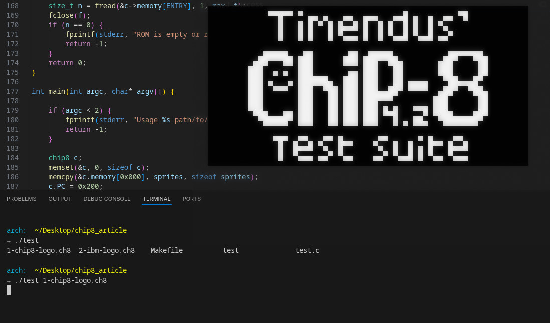
THE END
In part two we'll implement the keypad, other instructions and our timers :)
Comin soon,